
Behind the Label
How white-labelling, multi-vendor sourcing and weak integration inflate the cost of camera and motion-capture modules - and how co-engineering fixes it.
Abstract
Buyers of camera and motion-capture modules compare datasheets. But cost, reliability and time-to-market are decided by things a datasheet doesn't show: who built the module, how many vendors sit between the component maker and the buyer, and whether the camera, the inertial sensor and the compute board were designed to work together.
This paper explains how white-labelling works in the camera-module market. It then compares three common sourcing routes: a complete module from one supplier, a self-assembled camera-plus-SBC combination, and a full custom ODM programme. For each, it shows where cost and risk build up. Finally, it describes Mytron Lab's co-engineered model. We give the camera supplier and the SBC supplier the same specification and design synchronisation in from the start. We then validate the pair as one system and keep a service team behind the product. It closes with the three camera-plus-SBC kits Mytron Lab provides, priced from USD 200 to USD 300.
1. White-labelling is normal and not inherently bad - but it hides the bill of materials, stacks margins and often cuts the buyer off from engineering.
2. Buying a “complete” module means paying for every vendor layer in the chain. Assembling parts yourself means paying in integration time, rework and delay instead.
3. Synchronisation between the left/right cameras, the IMU and the compute board is the hardest property to add later - and the one that most affects data quality.
4. Co-specifying the camera and the SBC with their own suppliers removes the integration gap before the first unit ships.
1. Introduction
Wearable capture devices are moving from laboratories to factory floors. They are used for egocentric video, hand-task recording, and motion capture for robotics and embodied AI. A typical device needs five parts: a global-shutter stereo camera, an inertial measurement unit (IMU), a compute board to ingest and store the data, a battery and an enclosure. Each part is easy to buy on its own. Making them behave as one instrument is the hard part.
In our work on wearable stereo-camera and hand-motion recorders, the datasheet has rarely been the real problem. One commercially listed stereo module we evaluated left two things unclear [2]:
- The datasheet didn't say whether the unit shipped with its IMU fitted.
- H.264/H.265 output was in the feature list, but the resolution table documented only MJPG and YUY2 modes.
Neither is a defect. But ambiguities like these cost weeks once a project is under way.
This paper explains what happens behind a camera-module listing. It compares three ways to source a capture device and sets out why Mytron Lab works the way it does.
2. How the camera-module market works
2.1 Who makes what
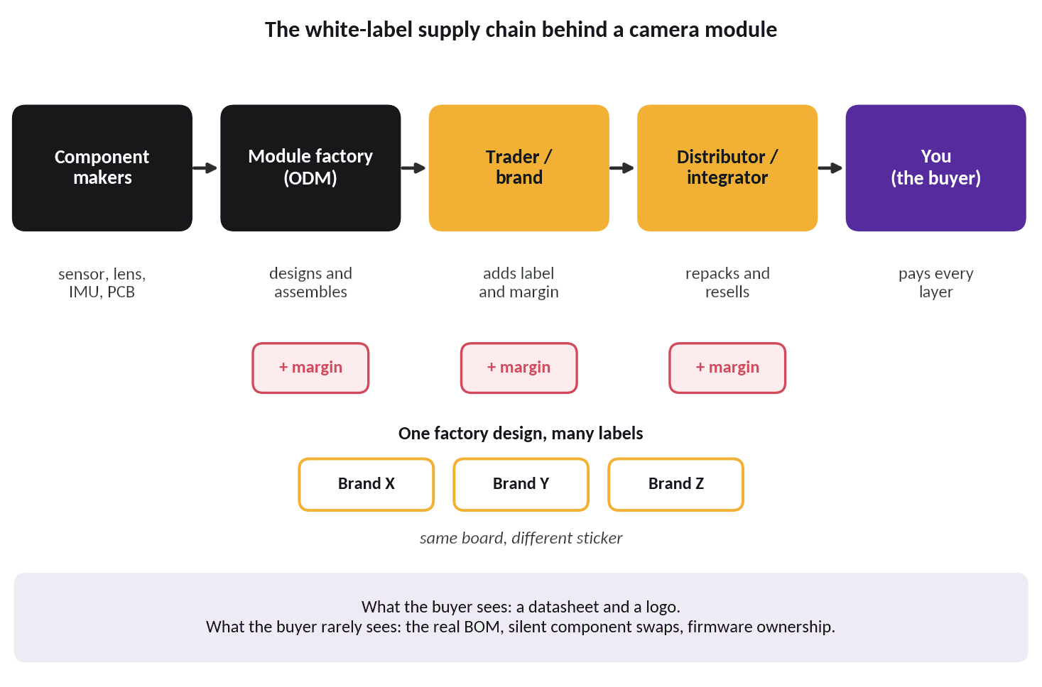
A camera module on a catalogue page is the end of a chain, not a single product. In Mytron Lab’s own vendor survey of eight suppliers, companies fall into three groups: system and wearable makers, camera-module OEM/ODM factories, and full-stack engineering partners [3]. The chain behind them looks like this:
- Component makers produce the image sensors, IMUs, USB or MIPI bridge chips and lenses. Typical sensors are global-shutter parts such as the onsemi AR0234CS (1920×1200, up to 120 fps) [7] and the SmartSens SC132GS [8]. A typical IMU is the TDK ICM-42688-P [9].
- Module factories (ODM/OEM) buy those parts through distributors. They design the PCB, assemble the board, align the lenses, flash the firmware and calibrate.
- Traders and brands put their name on a factory design. They may add packaging, a firmware skin or an SDK wrapper.
- Distributors and integrators repack and resell, sometimes bundling a compute board.
2.2 What white-labelling is, and what it isn't
White-labelling means that one factory design is sold by several companies under different names. It is a legitimate and common way to bring products to market quickly [6]. The risks for a buyer are practical rather than ethical:
- Opaque BOM. The sensor, lens, IMU or bridge chip can differ between batches without notice.
- Stacked margins. Each layer adds its own markup (Figure 2).
- Distance from engineering. A question about timestamps, trigger pins or drivers travels through a salesperson to the factory and back.
- Diluted support. Warranty and firmware updates depend on the reseller’s relationship with the factory.
- Spec drift. The listing, the datasheet and the unit in the box may not agree.
2.3 Where the cost accumulates
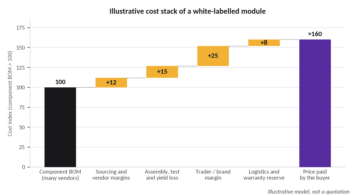
Figure 2 shows the structure of the problem with an illustrative model. In our illustrative model, a module with a component BOM of 100 reaches the end buyer at about 160. The exact figures differ by product and supplier. The structure does not.
In September 2026 we benchmarked nine suppliers and found a wide spread [1]:
- a verified monocular full-HD module with IMU at about USD 33;
- a global-shutter stereo module with IMU at about USD 95;
- turnkey head-mounted devices at about USD 300–400;
- a modular capture system at about USD 961.
At 10,000 units, the cheapest module path came out about twelve times cheaper than the most expensive turnkey device. These are different product tiers, not like-for-like quotes. Still, the gap shows how much of a finished device's price is integration, packaging and channel margin rather than sensing hardware.
3. Three ways to source a capture device
Each route below is rational in some circumstances. The aim is to show what the buyer really takes on in each case. A side-by-side comparison follows in Section 6.
Case 1 - A complete module from a single supplier (Supplier A)
Scenario. The buyer orders a finished camera-plus-IMU module, sometimes with a compute board, from one supplier. Purchasing is simple: one invoice, one datasheet, one contact.
What actually happens. Supplier A rarely makes everything it sells. It buys sensors, lenses, IMUs, PCBs and connectors from multiple vendors, then assembles and resells the result. Each vendor earns a margin; Supplier A adds assembly, test and its own margin on top (Figure 2). The buyer pays for the whole chain.
- Highest price for the sensing hardware received. The buyer cannot negotiate component by component because the BOM is not visible.
- Locked firmware and calibration. Any change needs the supplier’s engineers, and the supplier may route requests through a sales channel.
- Single-source dependency. If a component is swapped or discontinued, requalification falls on the buyer.
- The integration gap remains. A “complete” module still has to be made to work with the buyer’s own compute board, storage and power design.
Convenient to buy, expensive to own. The buyer pays for every layer in the chain and still carries the system-level integration.
Case 2 - Camera from Supplier A, SBC from Supplier B, assembled in-house
Scenario. To save money or gain control, the buyer purchases a camera module from Supplier A and a single-board computer from Supplier B and integrates them.
What actually happens. On paper both products are good. In practice nobody has tested them together, so every interface becomes a project of its own (Figure 3).
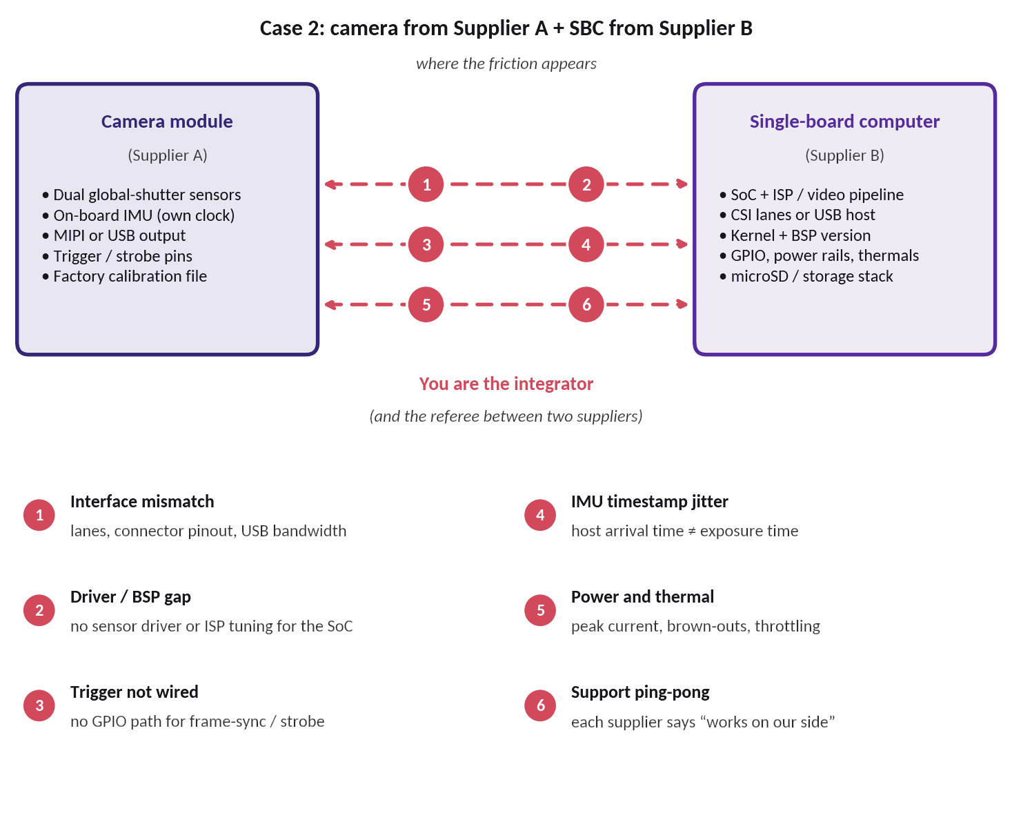
| Friction point | What it looks like | Typical consequence |
|---|---|---|
| Interface mismatch | A dual-MIPI stereo module with a 22-pin FFC meets a compute module that exposes a single 2-lane CSI input [2] | Bridge board, driver work or a different SBC |
| Driver / BSP gap | Whether a vendor SDK has a prebuilt ARM/Linux build for the chosen board can be an open question on which the controller choice depends [3] | Weeks of porting or a re-selection of the SBC |
| Trigger not wired | Frame-sync and strobe pins exist on the camera but have no routed path on the SBC | Left/right frames and IMU data drift apart |
| IMU timestamp jitter | IMU data reaches the host over USB and is stamped on arrival, not at exposure | Motion data cannot be aligned precisely with video |
| Power and thermal | A camera drawing up to 320 mA at 5 V sits on a battery and boost design never tested with it [3] | Brown-outs, resets, throttling in the field |
| Support ping-pong | Each supplier confirms its own product works in isolation | The buyer becomes the integrator and the referee |
In one of our own evaluations, four questions had to be answered by the vendor before the design could even be frozen: whether the IMU was fitted, whether a prebuilt ARM/Linux SDK existed, whether the mating cable shipped in the box, and whether H.264/H.265 output actually worked [3]. Each answer arrived through a different channel and a different delay.
Cost. Parts look cheap, but the buyer also pays for engineering hours, several sample rounds, extra shipping, delay, and most importantly - a synchronisation quality that ends up lower than it would have been if the two sides had been designed together.
Cheap parts, expensive system. The saving on the bill of materials is spent several times over on integration, rework and time.
Case 3 - A full custom ODM programme
Scenario. The buyer commissions a custom design from an ODM, or designs its own sensor head and PCB (for example global-shutter sensors, an FPGA and a USB 3.0 bridge).
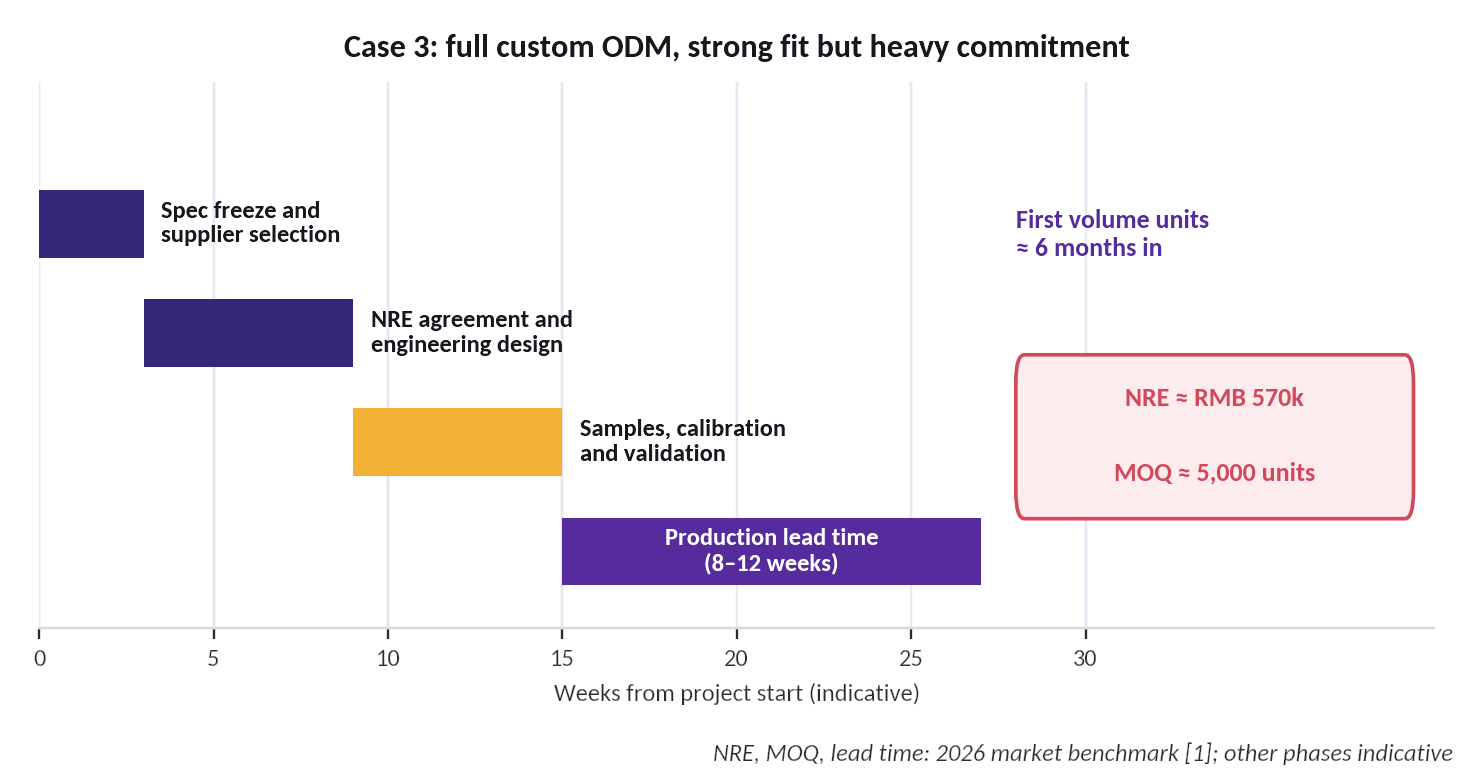
What actually happens. A custom path can match the specification almost exactly and gives the lowest unit cost at scale. In the 2026 benchmark [1], the best custom ODM path scored highest overall (90/100) at about RMB 320 (USD 44) per unit - but required about RMB 570,000 of non-recurring engineering (NRE), a 5,000-unit minimum order quantity (MOQ) and an 8–12 week production lead time (Figure 4).
- Large up-front commitment. NRE and MOQ must be committed before field experience exists.
- The buyer owns the hard parts. Specification, calibration process, test fixtures and firmware all sit with the buyer unless an engineering partner is hired.
- Self-designed sensor heads need rare skills. FPGA design, USB 3.0 firmware, optics and calibration are each specialist areas.
- Change is expensive. A new sensor, lens or interface after tooling restarts much of the cycle.
The right answer at high volume with a frozen specification. For most teams earlier in the journey, the commitment arrives before the evidence.
4. Why synchronisation decides data quality
4.1 What has to be synchronised
A hand-task recorder produces several streams that only make sense together:
- the left and right images, for depth;
- the IMU, for motion and orientation;
- the host clock, for logs and file names.
Each extra sensor adds another clock domain. A data glove, for example, may output at 120 Hz with under 10 ms latency [4], which doesn't match a 30 fps camera.
4.2 Hardware timestamps versus software timestamps
Free-running sensors are stamped when their data arrives at the host. Arrival time includes USB or MIPI transfer delay, operating-system scheduling and buffer jitter, so it can differ from the real exposure time by many milliseconds (Figure 5a). A hardware-triggered design exposes both cameras from the same trigger edge and latches the IMU timestamp to that edge, so every sample is tied to the moment light reached the sensors (Figure 5b).
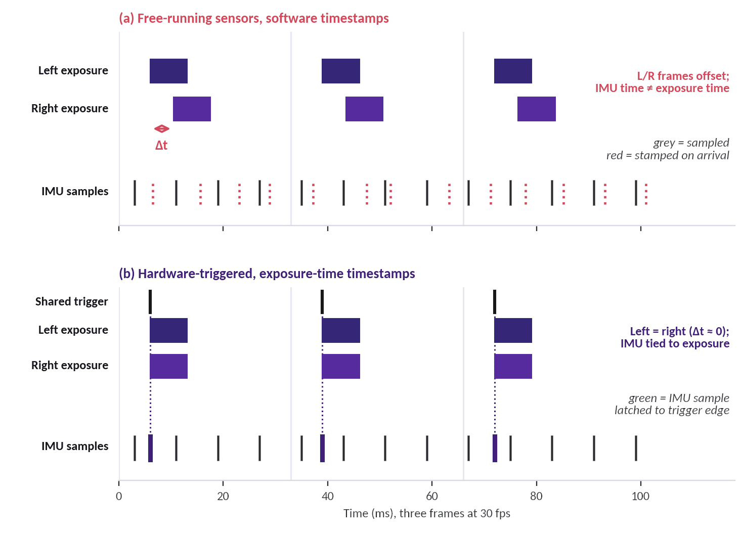
The consequence is physical. Timing error multiplied by hand speed is position error:
| Timing error | Position error at 1 m/s hand speed | Comment |
|---|---|---|
| 0.1 ms | 0.1 mm | Hardware-synchronised target range |
| 0.5 ms | 0.5 mm | Typical camera-to-IMU acceptance limit in demanding programmes [5] |
| 2 ms | 2 mm | Minimum sync tolerance used in the 2026 benchmark [1] |
| 10 ms | 10 mm | Visible misalignment of fingertips against depth |
| 33 ms | 33 mm | One full frame at 30 fps |
4.3 What good looks like
Acceptance criteria in a wearable-tracking programme we have supported were strict [5]:
- camera-to-camera synchronisation below about 100 µs preferred;
- camera-to-IMU below 500 µs;
- left-to-right colour cameras below 500 µs;
- timestamps that represent exposure, not software arrival.
Our 2026 benchmark set a minimum sync tolerance of 2 ms or better. It also required global shutter, factory calibration and an IMU of at least 250 Hz [1]. A global shutter exposes all pixels at once, which avoids the row-by-row skew a rolling shutter produces during fast hand movement [10]. Residual offsets can be estimated after the fact with online temporal calibration [11] or tools such as Kalibr [12], but only if the hardware gives them a stable signal to measure.
4.4 Why it cannot be retrofitted
Synchronisation is a property of the module, not the compute board. It needs three things:
- trigger and strobe lines routed on the camera PCB;
- an IMU mounted rigidly on the same board, so it shares the cameras' frame of reference;
- firmware that stamps data at exposure.
If a module was designed without these, no SBC can add them afterwards. That is the main reason co-engineering has to start at the camera module, and why Case 2 so often disappoints.
5. The Mytron Lab approach: co-engineered camera and SBC
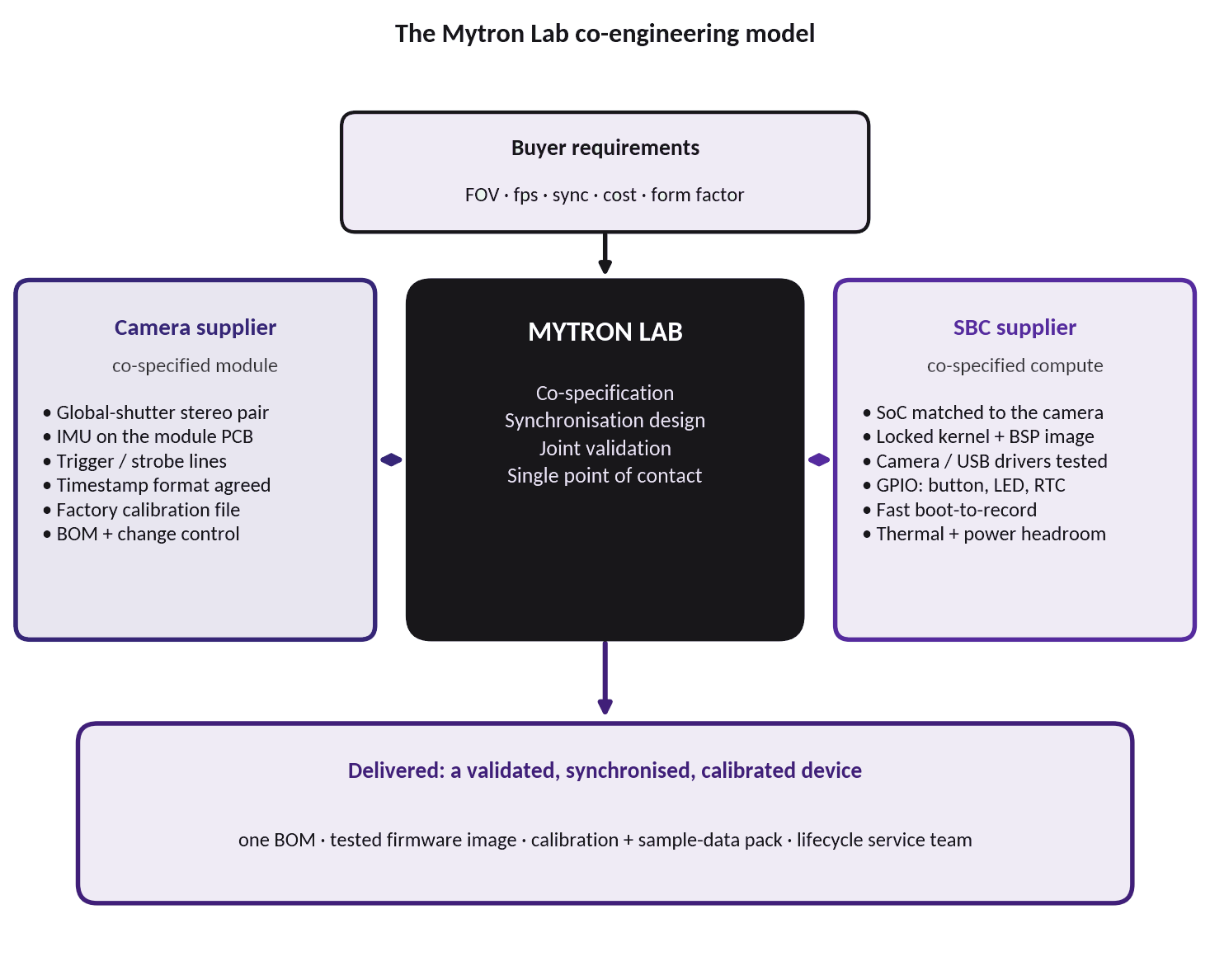
Mytron Lab treats the camera module and the compute board as one product with two manufacturers. We collaborate with the camera supplier and with the SBC supplier, give each the same specification, design the synchronisation across both, validate the pairing ourselves, and stay accountable after delivery (Figure 6).
5.1 Co-specify with the camera supplier
We work with the camera supplier to define the module rather than choosing from a catalogue. The shared specification covers:
- sensor, lens and field of view, with a global-shutter stereo pair on a defined baseline;
- an IMU integrated on the module PCB, so it moves rigidly with both cameras;
- trigger, strobe and frame-sync lines brought out and documented;
- the timestamp format and the point in the pipeline where it is applied;
- a factory calibration file per unit (intrinsics, distortion, extrinsics);
- BOM transparency and change control, so components are not substituted silently.
5.2 Co-specify with the SBC supplier
The same discipline applies on the compute side. We select the SoC and board to match the camera interface instead of adapting the camera to whatever board is cheapest, and agree with the SBC supplier:
- a locked kernel and board-support-package (BSP) image with the camera and USB drivers already tested;
- GPIO allocation for the button, status LED and real-time clock;
- an auto-start capture service and a boot-to-recording time that meets the product requirement;
- storage handling (microSD, exFAT) that survives power loss, and power and thermal headroom for the camera load.
5.3 Design synchronisation in, then measure it
With both suppliers working from one specification, the trigger path, the clock relationships and the timestamp origin are designed once, for the pair. We then verify them against measured sample data - recorded video, the IMU log and the calibration files - rather than relying on datasheet numbers alone, in line with the sample-validation practice in the RFQ checklist of the 2026 benchmark [1].
5.4 One bill of materials, one validated image, one contact
The buyer receives a single, documented BOM, a firmware image that has been tested on the exact hardware pairing, and one team to call. There is no referee role to play between two suppliers.
5.5 Commercial effect
- Fewer margin layers. Components are sourced through the co-specified factories instead of through a chain of traders.
- Consolidated volume. Requirements from several projects can be combined, and price ladders (for example at 100, 1,000, 5,000 and 10,000 units) are requested from both suppliers.
- Less integration spend for the buyer. The engineering that Case 2 leaves with the buyer has already been done.
- Lower rework risk. Interfaces, drivers and sync are validated before volume production.
5.6 What we provide: three ready camera + SBC kits
Mytron Lab works with more than one camera manufacturer and more than one SBC manufacturer, so each kit is matched to the budget and to what the capture must deliver. Table 1 lists the three kits we provide, from an entry-level kit to a performance kit.
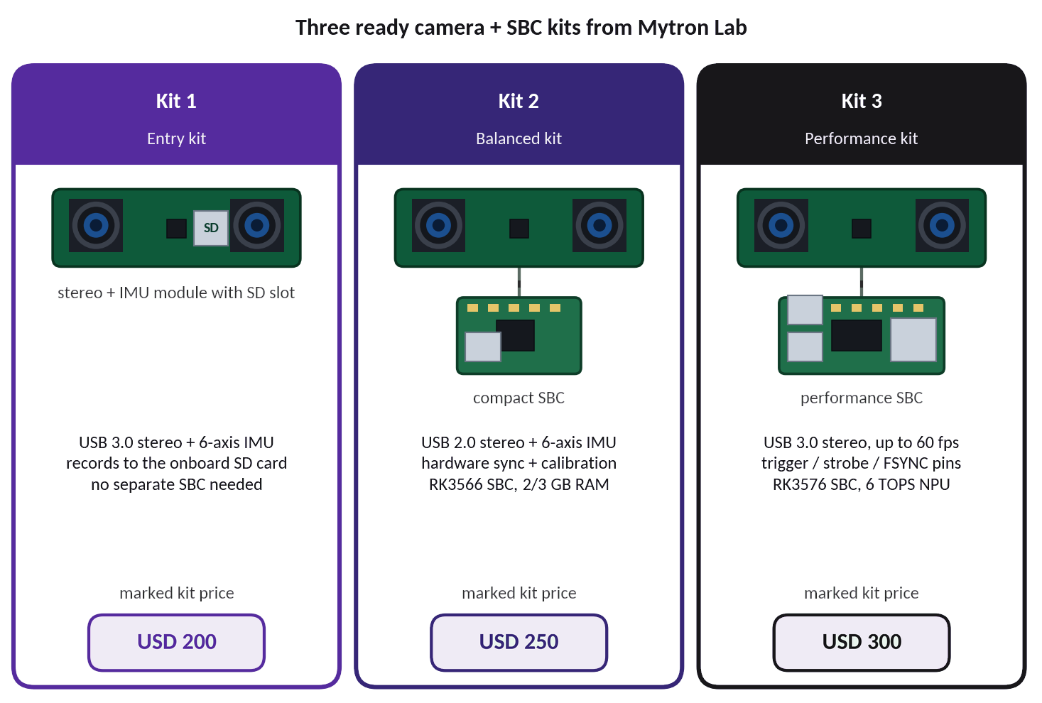
Table 1. Camera + SBC kits provided by Mytron Lab.
| Kit (camera module) | SBC module | Brief specifications | Price |
|---|---|---|---|
| Kit 1 — Entry USB 3.0 stereo camera module with onboard SD-card recording | Not required Records to the onboard SD card | Dual global-shutter sensors, 2 × 1920×1200 at 30 fps USB 3.0 Type-C (UVC), MJPG / H.264 / H.265 6-axis IMU, 164° diagonal field of view, −30 to 60 °C | USD 200 |
| Kit 2 — Balanced 1080P global-shutter stereo camera module with IMU, USB 2.0 | Quad/Hexa core SBC 2/3GB RAM variant | Global-shutter stereo, 1080p / 1200p at 30 fps (MJPG), 123° diagonal field of view 6-axis IMU up to 500 Hz, hardware sync, factory calibration SBC: 4 × Cortex-A55 at 1.6 GHz, ~0.8 TOPS NPU, Wi-Fi 6 / BT 5.4 | USD 250 |
| Kit 3 — Performance Dual AR0234 global-shutter stereo camera module, USB 3.0 | Octa core SBC 4/6GB RAM variant | 2 × 1920×1200 at 60 fps (MJPEG), USB 3.0 Type-C (UVC) 6-axis IMU at 600 Hz, trigger / strobe / FSYNC pins, 166° default field of view (lens options 92–200°) SBC: 4 × Cortex-A72 + 4 × A53, 6 TOPS NPU, 2 × USB 3.0, Gigabit Ethernet | USD 300 |
Specifications are taken from the manufacturers’ documentation and are confirmed on sample units during validation. Prices are indicative marked kit prices and are subject to final quotation, quantity and configuration.
Every kit follows the co-specification, synchronisation and validation steps described above. The difference between the kits is where the effort concentrates, not whether it is done.
5.7 Service and lifecycle support
A device in the field needs more than a warranty. Mytron Lab maintains a team to support products after delivery, including firmware and image updates under version control, replacement and spare-part handling, re-calibration, notification and requalification when a component changes, field troubleshooting, and support for future revisions such as moving analysis onto the device. Service terms are agreed per project.
5.8 What a co-engineered device can look like
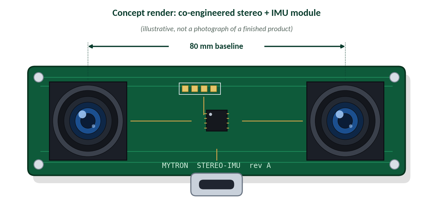
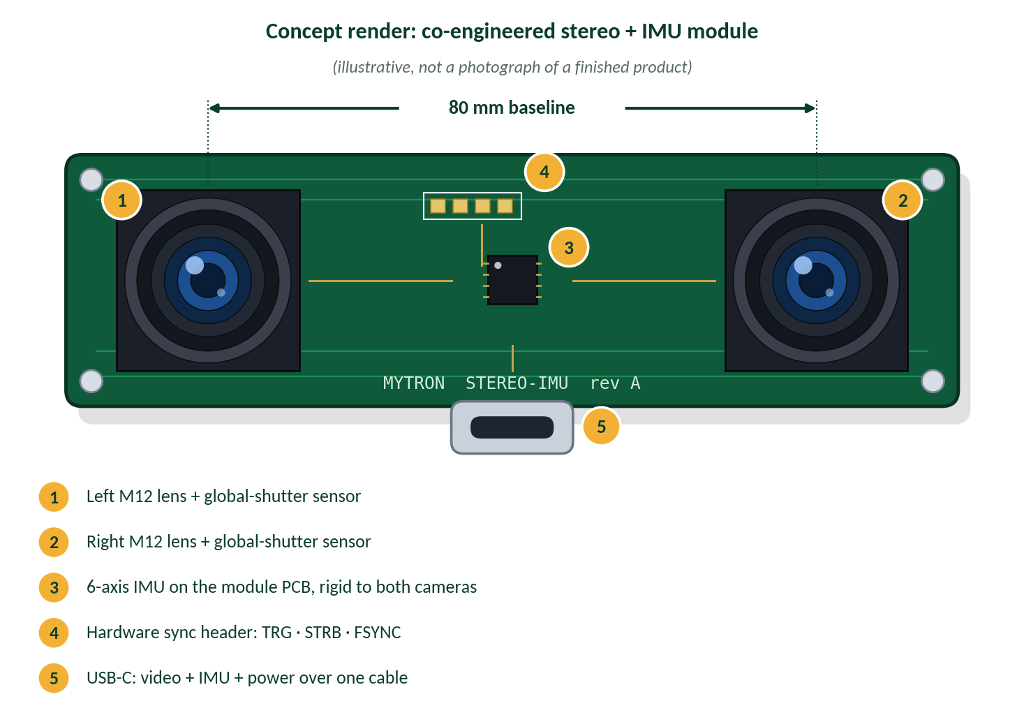
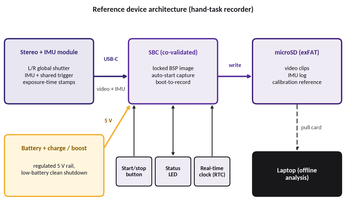
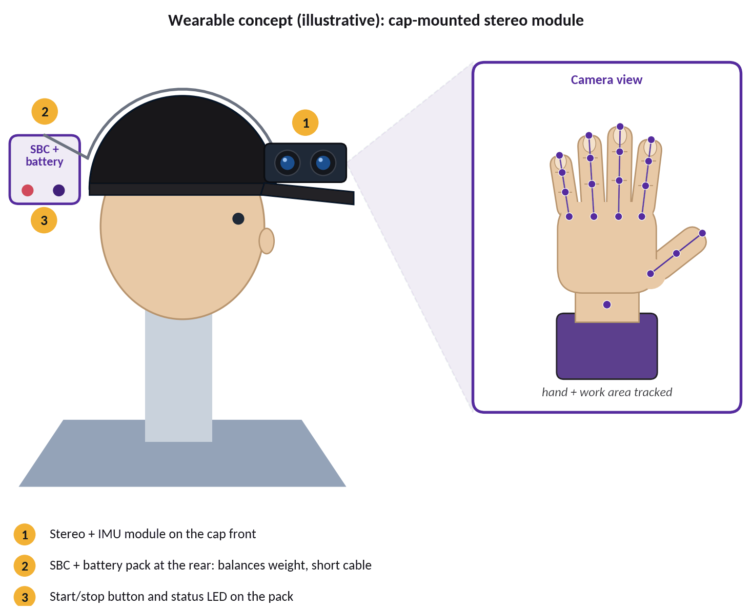
Figures 8-10 are concept illustrations of the kind of device this approach produces: a stereo and IMU module with a documented sync header and a single USB-C connection (Figure 8), a short, auditable signal chain from camera to storage (Figure 9), and a cap-mounted wearable with the compute pack at the rear (Figure 10).
6. Comparative evaluation
6.1 Side-by-side summary
The table gives Mytron Lab’s qualitative assessment of the four routes. Lavender indicates a strength, amber a trade-off and red a significant risk for the buyer.
| Criterion | Case 1 Complete module | Case 2 Mix & match | Case 3 Custom ODM | Mytron Lab co-engineered |
|---|---|---|---|---|
| Up-front commitment | Low | Low | Very high (NRE, MOQ) | Low |
| Unit cost | High | Low parts, high total | Lowest at scale | Competitive |
| Integration effort for buyer | Medium | High | High | Low |
| Synchronisation | Depends on supplier | Left to the buyer | Designed in | Designed in and validated |
| Customisation | Limited | Full, self-funded | Full | Co-specified |
| Time to first working unit | Fast | Slow | Slow | Short (pairing pre-validated) |
| Long-term support | Reseller-dependent | Two suppliers | Buyer-owned | Dedicated service team |
6.2 Total cost of ownership
Unit price alone misleads. Figure 11 adds the costs that appear only after the purchase order: integration and debugging effort, rework and delay, support, and amortised NRE. The model is illustrative, uses a pilot scale of about 1,000 units, and states its assumptions in Appendix A.
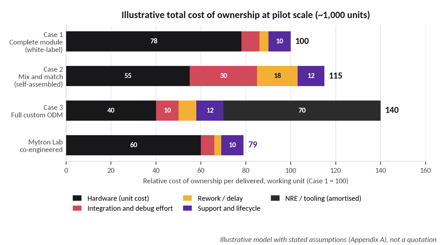
Two patterns stand out. The self-assembled route (Case 2) has a modest hardware cost but the largest integration and rework share. The custom ODM route (Case 3) has the lowest hardware cost, but at pilot scale its
NRE dominates; its economics only turn favourable at the volumes in the benchmark [1]. The co-engineered route sits lowest at pilot scale because it removes the stacked margins of Case 1 and the integration and rework burden of Case 2 without the NRE of Case 3.
7. A buyer’s checklist for any supplier
Whichever route is chosen, these questions separate a datasheet from a deliverable. They are adapted from the RFQ and sample-validation checklist in the 2026 benchmark [1] and from our own project experience [3].
| Area | Ask for | Why it matters |
|---|---|---|
| BOM and change control | Sensor, lens, IMU and bridge part numbers; written notice of substitutions | Prevents silent component swaps between batches |
| Shutter and sensor | Rolling vs global shutter; resolution and frame rate in each output mode; encoding actually supported | Avoids listing-versus-unit mismatches |
| IMU | Model, output data rate, ranges, timestamp format, whether it is fitted to this exact unit | Motion data quality and alignment |
| Synchronisation | Trigger architecture, clock source, timestamp origin, measured sync tolerance | Defines depth and motion accuracy |
| Calibration | Intrinsic and extrinsic files, distortion model, factory process, repeatability | Needed for metric depth and camera-IMU fusion |
| SDK and OS | Prebuilt ARM/Linux builds, raw-stream access, export method, driver status on your SBC | Prevents Case 2 surprises |
| Sample data | Recorded video, IMU log, calibration file and sync documentation from the actual unit | Evidence instead of claims |
| Power and thermal | Peak and average current, operating temperature range, soak-test results | Field reliability on a battery-powered wearable |
| Commercial terms | Unit price at 100 / 1k / 5k / 10k, MOQ, lead time, quote validity, warranty | Avoids hidden volume or validity traps |
| Lifecycle | Firmware update path, spares, RMA process, end-of-life notice period | Cost and risk after delivery |
8. Conclusion
Behind most camera-module listings sits a chain of vendors, each adding margin and distance. The three routes each pay for it differently:
- Buying the complete module (Case 1) pays for the whole chain.
- Assembling the parts yourself (Case 2) swaps that margin for integration risk.
- A custom ODM programme (Case 3) trades cash and time for the lowest long-run unit cost.
In all three, synchronisation quietly decides data quality, and synchronisation is decided at the module level. That is why Mytron Lab works with the camera supplier and the SBC supplier together. Both get the best specification we can define, and the synchronisation is designed across the pair. We then validate the combination as one system and keep a service team behind it.
For the buyer, the outcome is practical:
- a more reliable device;
- a lower total cost of ownership;
- a clear owner for every question;
- a partner for the next revision.
The three ready kits in Section 5.6, priced from USD 200 to USD 300, show how this applies across budgets.
Appendix A — Notes on the illustrative figures
- Figure 2 (cost stack). Index values are an illustrative structure: component BOM 100, plus vendor margins 12, assembly/test/yield 15, trader margin 25, packaging/logistics/warranty reserve 8. They are not supplier quotations.
- Figure 11 (total cost of ownership). Assumes a pilot volume of about 1,000 units, NRE amortised over those units, and integration and rework effort valued as engineering time. The co-engineered route assumes direct purchasing from co-specified factories at consolidated volume with no trader margin.
- Table 1 and Figure 7 (kits). Specifications come from manufacturer documentation and are subject to confirmation on sample units; kit prices are marked indicative prices and are subject to final quotation. Figure 7 is an illustrative drawing.
- Figure 4 (custom ODM). NRE, MOQ and production lead time are taken from the 2026 benchmark [1]; the earlier phase durations are indicative.
- Figures 8–10 and the cover image. Concept illustrations drawn for this paper; they do not depict a finished or shipping product.
Appendix B — Glossary
| Term | Meaning |
|---|---|
| White-label | A product made by one company and sold under other companies’ brand names |
| OEM / ODM | Original equipment / design manufacturer: a factory that builds, or designs and builds, products for others |
| SBC | Single-board computer: a compact board with processor, memory and I/O that runs the capture software |
| BSP | Board support package: the kernel, drivers and boot configuration for a specific board |
| MIPI CSI / UVC | Camera-sensor interface used on embedded boards / standard USB video class |
| Global shutter | All pixels exposed at the same instant, avoiding skew in fast motion |
| IMU | Inertial measurement unit: accelerometer and gyroscope, sometimes with a magnetometer |
| Baseline | Distance between the two stereo camera centres |
| NRE / MOQ | Non-recurring engineering cost / minimum order quantity |
| Exposure-time timestamp | A timestamp applied when the sensor is exposed, not when data arrives at the host |
References
- 1. Mytron Lab, Market benchmark of nine camera-module suppliers, September 2026.
- 2. Mytron Lab, Stereo-module evaluation notes and vendor Q&A, 2026.
- 3. Mytron Lab, Vendor survey of eight camera and wearable suppliers, 2026.
- 4. Supplier catalogue listing for a commercial data glove (120 Hz output, <10 ms latency), reviewed 2026.
- 5. Acceptance criteria from a wearable-tracking customer programme, shared under NDA.
- 6. VentureOutsource, “Top 10 global surveillance camera companies and their supply chain dynamics”, 25 September 2025.
- 7. onsemi, AR0234CS 1/2.6-inch 2.3 MP CMOS digital image sensor with global shutter, product page; specifications summarised by GoPhotonics.
- 8. SmartSens, SC132GS 1.3 MP global-shutter CMOS sensor, specifications via GoPhotonics.
- 9. TDK InvenSense, ICM-42688-P 6-axis MEMS motion-tracking device, product page (external clock input, I3C/I²C/SPI).
- 10. Axis Communications, “Global shutter vs rolling shutter”, white paper.
- 11. T. Qin and S. Shen, “Online Temporal Calibration for Monocular Visual-Inertial Systems”, IEEE/RSJ IROS, 2018.
- 12. P. Furgale, J. Rehder and R. Siegwart, “Unified Temporal and Spatial Calibration for Multi-Sensor Systems”, IEEE/RSJ IROS, 2013; implemented in the open-source Kalibr toolbox.